6. Assembly
Rotor balancing
Each rotor should be balanced, or the PMG will shake when it is turning. The whole
PMG needs to be balanced again at the end, because the rotors may not be mounted
exactly centrally. A different procedure is used for the final balancing in Section 6.
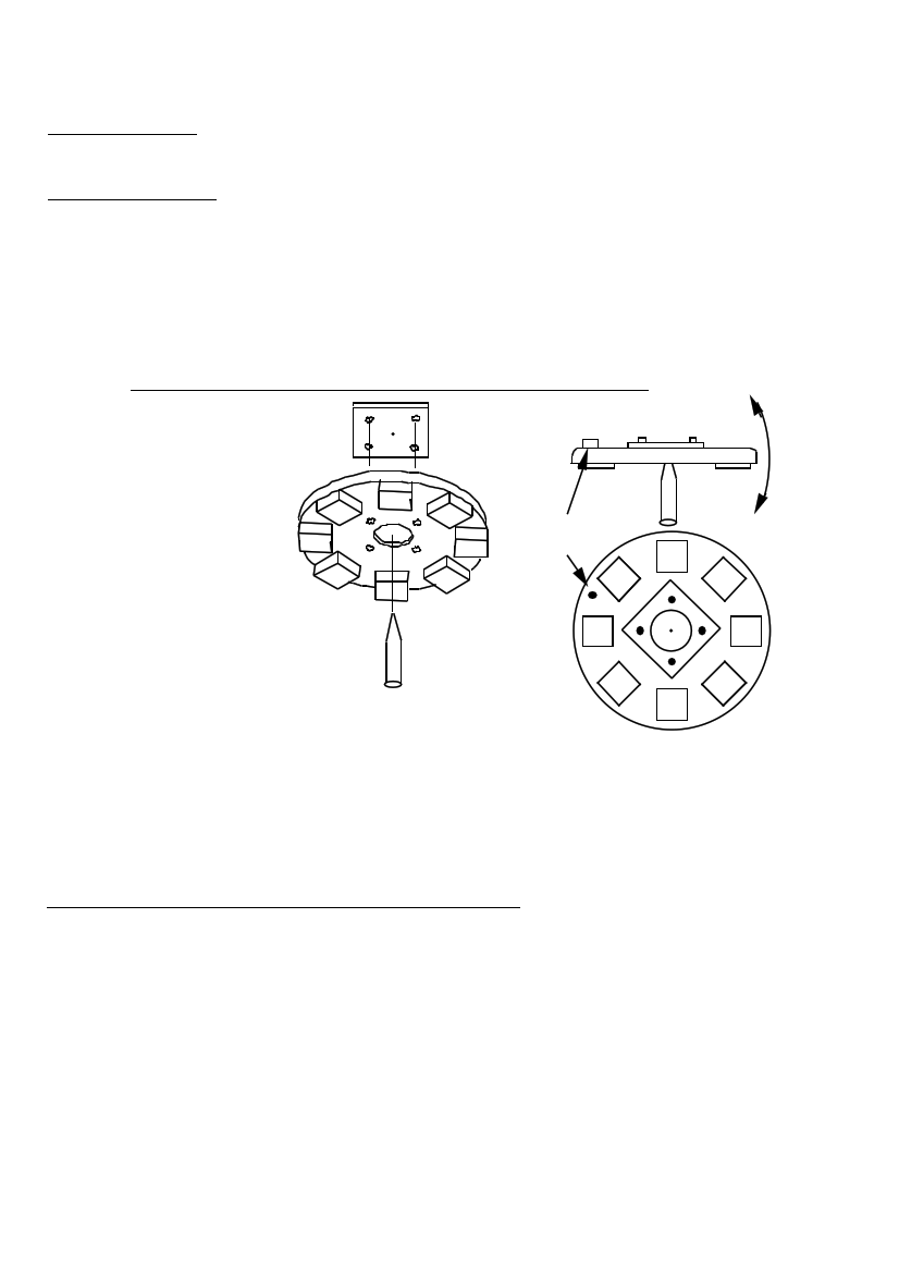
To balance a magnet rotor (see diagram 38), first attach the PCD jig (from diagram
11), using four bolts. Then balance the rotor on a spike as shown:
38. ASSEMBLY OF THE BALANCING JIG AND SPIKE
PCD JIG
MAGNET ROTOR
SMALL
WEIGHT
SPIKE
If the rotor will sit level, then it is balanced. If it will not sit level, then add small
weights to it, or drill out some of the resin between magnets, until it will sit level.
Turn the PCD jig around on the rotor, and check it again. Replace any weights with
pieces of M10 threaded rod, screwed into holes in the resin between the magnets.
PMG spine and bearing hub (see diagram 39)
Make the spine of the PMG from a 380mm length of 'box section' steel tube
50x25x4mm (sometimes called RHS). Mark the exact centre of one large face, and
then mark four 8mm holes, in the same way as for the 'stator studs jig'. It could
also be possible to use the stator studs jig to help drill the holes.
The hole at the centre is 25mm (or to suit the shaft used). Drill this with a hole-
saw, or bore it on a lathe.
PMG manual
page 36
June 2001